The UK quattro Network
The UK's mobile Audi 5-cylinder mechanic - 07833 654800, 24x7
Specialist in turbos, quattros, electrics and non-starts
Test - Oil Warning Light and Buzzer - Audi ur-quattros
In the event of either a red oil pressure warning light or an audible warning from the speech synthesizer system, switch the engine off immediately and seek assistance.
Prerequisites in testing:
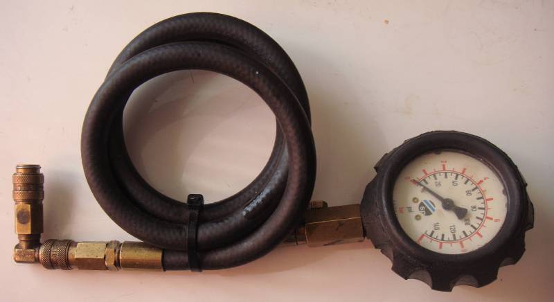
To minimize risk to the engine, check the oil level via the dipstick and the actual oil pressure with a mechanical Bourdon-type gauge (spark plugs removed) before performing these tests. Low oil pressure can be caused by the wrong oil, a stuck oil pressure relief valve (held in by the oil temperature sender - extreme front and bottom of engine) or by engine wear, typically the main and big end bearings. Do not proceed with these tests unless satifisfied that actual oil pressure is adequate. False warnings can be generated if water leaks onto the auxiliary relay panel behind the glovebox - ensure this area is dry before continuing.

A Sykes-Pikavant Bourdon oil pressure gauge with Audi fittings
- Engine filled to two rows of dots below maximum with correct grade of oil
- Oil pressure checked with mechanical gauge
- If the oil warning light does not light when the ignition is switched on, check the dashboard bulb, oil pressure sender (G10) and the controller.
- Oil temperature must be at least 80°
- Rev counter must be functioning normally
Procedure for checking the sender (G10) on the side of the engine block - MB and RR engines:
- Remove the connector from the oil pressure sender G10 contact "G".
- Connect an ohmmeter to contact G on G10 via an extension cable and to chassis ground.
- Switch the ohmmeter to the 200 ohm range.
- With the engine off, the reading should be 5 to 10 ohms.
- With the engine idling, the reading should be 70 to 120 ohms.
- With the engine at 3000rpm, the reading should be 170 to 200 ohms.
- Attach the ohmmeter between contact WK (unused) on G10 and chassis ground.
- With the engine idling, the resistance should be zero to 0.5 ohm.
- With the engine off, the resistance should be infinite.
- If any of the preceding tests fail, replace G10. The tests should then be repeated, since it is possible for the PTFE tape now used on new sender threads to interfere with electrical conductivity to the block, which is used as the return circuit.
Procedure for checking oil warning lamp control unit - MB engine. If the diode light in use is polarity-sensitive, try reversing the probe points before considering the test failed:
- Remove the glovebox
- Pull the control unit out of its position (6 - centre row, extreme right, "234" on top) in the auxiliary relay carrier.
- Connect a diode check light (Gunson from Halfords or VAG 1527) to contacts 4 and 5 of the socket.
- Switch on the ignition. The diode must light up. If still dead, check for a circuit fault using the circuit diagram.
- Connect the diode check light between contacts 5 and 8 of the socket.
- Turn the engine over with the starter motor. The diode check light must blink during the start procedure, and glow steadily with the motor running. If not, check for a circuit fault using the circuit diagram.
- Connect the diode check light between contacts 2 and 4 of the socket.
- Switch the ignition on. The diode must light up. If not, check the oil pressure sender and/or the circuit for faults.
- Pull the connector G off the oil pressure sender G10. The diode must not light up. If it does, check for a short circuit using the wiring diagram.
- Connect contact 6 of the socket to chassis ground using a piece of wire. The oil warning light must light up. If not, check for a circuit fault using the wiring diagram.
- If all tests are completed successfully, replace the J114 control unit.
Kerbside Motors Home Page

