| | See page 18.
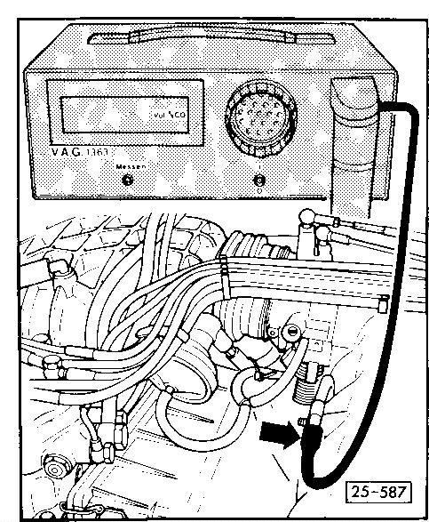
The engine has FEI, no ignition timing point check.- Connect up test appliance for ignition timing, engine speed (e.g., VAG 1367) with ignition switched off.
 | Note:
To connect up to terminal one, the coil cover must be removed on engines that have two knock sensors.- Connect up hand multimeter VAG 1526 fr measuring current (mA) to idling stabilisation valve (N71) using auxiliary wires from VAG 1594 (with additional measuring wire VAG 1315/A2).
- Connect up CO measuring test appliance VAG1363
Note:
The hose must fit tightly on measuring pipe to ensure no exhaust gas leaks
| 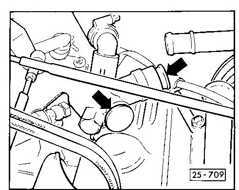 | Engines with one knock sensor:- Disconnect crankcase breather hoses from cylinder head cover and plug
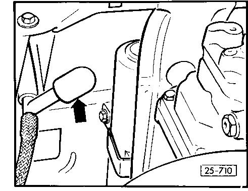 | - Remove sealing cap - arrow - from T piece in hose to activated charcoal filter
Note:
Angled piece must remain in air intake elbow since it has a calibrated drilling
|  | Engines with two knock sensors
- Disconnect plug from activated charcoal filter system solenoid
- Disconnect plug from angled piece of air intake elbow
Note:
Angled piece must remain in air intake elbow since it has a calibrated drilling- Remove sealing cap from CO measuring pipe
| 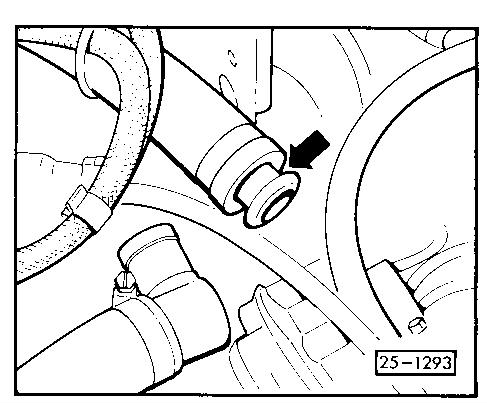 | - Disconnect crankcase breather hose between air intake elbow and cylinder head cover and plug with sealing cap of CO measuring pipe
| | Checking and adjusting idling speed/idle stabilisation and CO content
- Start engine and run at idling speed. Read display on hand multimeter
If required, the specified value can be corrected with idling speed adjustment screw
If specifications are not attained, check idling speed stabilisation (repair measure)
| 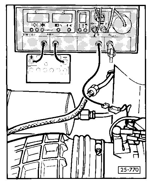 | - Measure duty cycle (dwell angle) with tester VAG 1367
- Disconnect tester cable from contact 1 on ignition coil and connect to blue/white cable of Lambda test connection
- Disconnect adapter clip from HT cable (cylinder 1)
- Press % button on tester
Note:
Ignore visual speed display on tester- Check duty cycle (dwell angle display)
| | Note:
If CO content is more than 1.2% volume at a duty cycle of 25% to 65%, the following malfunctions may be present:- Ignition system not OK
(checking and servicing - repair measure - Leaky exhaust system (repair leaks or renew parts - repair measure
- Fuel metering distributor defective (unequal injection quantities at idling speed.)
(Checking and servicing - comparative testing of injection capacity - repair measure)
| | If duty cycle is less than 25% or more than 65%, duty cycle must be adjusted with CO adjusting screw.- Switch off ignition
- Remove air intake elbow from metering distributor
- Centre-punch CO adjustment screw cap
- Using 2.5mm drill, drill a 3.5mm deep hole in cap
- Remove swarf
- Screw in 3.0mm diameter tapping screw
- Pull cap out with pliers
- Connect air intake elbow
- Start engine and run at liding speed
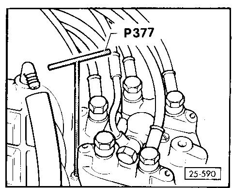 | Important:
When adjusting CO do NOTpress down or lift up the adjustment screw with the adjusting key.
Do NOT depress throttle with adjusting key in position (danger of bending).
Immediately remove adjusting key after each adjustment and give a short burst of throttle.- Adjust CO content with adjusting key P377 (a long 3mm Allen key)
- Clockwise increases CO content
Anti-clockwise decreases CO content - When adjusting the mean value should be aimed for
- Always increase CO content from decreased to increased value
- After adjusting CO content the idling speed stabilisation is to be checked, and if necessary corrected to specified value
- Lock adjustment screw with new anti-tamper cap #026 133 777
- After completing adjustment see notes on page 18
|
|
|
|
|
|
|