The UK quattro Network
The UK's mobile Audi 5-cylinder mechanic - 07833 654800, 24x7
Specialist in turbos, quattros, electrics and non-starts
The 1980 Audi ur-quattro was one of the very first cars whose engine was actually controlled entirely by a computer. But little provision was made for debugging, in contrast with modern cars that log out to diagnostic equipment in the workshop. Debugging some problems can be tough since it requires a combination of electrical and mechanical skills. Kerbside Motors uses a number of specially made test leads to ease this job.

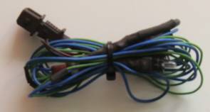
This was the first test lead made, over a decade ago. It has male and female connectors on a short piece of cable and plugs in between the wiring loom and the cold start injector, connecting a small lamp on a long lead across the valve. The length of the lamp lead allows the lamp to be taped near the driver so that cold start valve operation can be observed. The original purpose was to solve cold starting problems on WR, KG and similar Audi engines, and observe the 1B, MB, and MC engines use of the valve during acceleration. But similar connectors are used on many Audi engines - the wastegate frequency valve used on the I5 20-valve engines (RR, 3B, ABY, etc.) is another example.
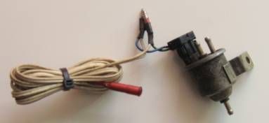
This was the second lead developed, at the suggestion of Scott Mockry. It has the unique connector used on the wastegate frequency valve found on Audi 1B, MB and MC-2 engines - see the attached valve in the photograph. This connects an LED light on a long lead to the valve - the LED flashes when the valve operates. The lead is primarily used to detect and debug limp home mode on these MAC-12 and MAC-14 controlled engines, since the fault code mechanism is not conclusive. It also has uses debugging some overboost conditions.
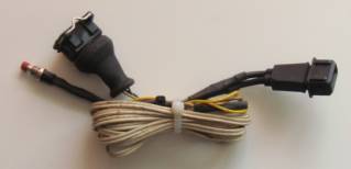
Very much a companion of the above lead and always used with it. This is interposed between the throttle body switch (also known as the WoT or full load switch. The WoT switch should close at about 55° throttle opening to cause full enrichment - the engine should go from approximately the stochiometric mean (14.2 parts of air to one of fuel) to the optimum power ratio of 12.4:1 for full power during acceleration. This switch is notoriously failure-prone because of a design flaw, but the failure is often not detected by the ECU diagnostics. The switch on the lead can be operated by the driver to simulate the throttle body switch closing, which should cause the LED on the wastegate frequency valve lead to flash if there are no other problems causing limp home mode.
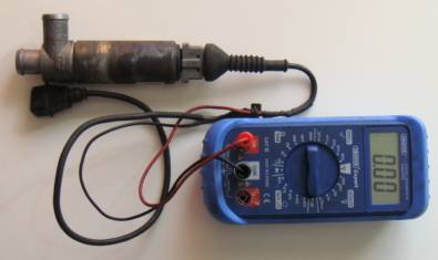
Again a lead specific to the Audi 1B,MB and MC-2 engines. Part of the process of setting such an engine up correctly involves measuring the effective current through the idle stabilization valve, to ensure the valve is operating precisely at the centre point of its range. Unfortunately the circuit is fickle - if it is broken at any time the car must be switched off and restarted. The photograph shows the lead with both a valve and multimeter attached. The signal is actually a 60Hz pulse - the pulse width being adjusted by the idle stabilisation controller for an ideal 430mA. The idle stabilisation controller has no output devices, and can only signal that it has a problem by setting the current to exactly 470mA. This error message can only be read with a lead such as this.
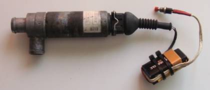
The idle stabilisation valve is not operated to chassis ground - both power and return come from the ISV controller. It is also not designed to be exposed to a full 12V supply, so this test lead was developed to test it using a 9V alkaline battery with a high internal resistance.
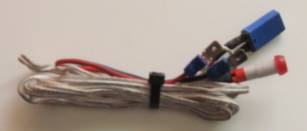
As the ur-quattro developed, more and more electrical devices were added to the car. Although it's sometimes hard to believe, there is an underlying logic to the ur-quattro's wiring. Fuse 12 supplies a circuit that runs all over the car supplying "occasional current users" such as the reversing lights, horn, etc., and was relentlessly added to over the years. Fuse 12 blowing is a nightmare to debug. This lead is inserted into any fuse slot - it has a 10A self-resetting thermal cutout with an LED connected across it - if the cutout opens, the LED lights. After a few seconds, the thermal cutout resets and the LED goes out. If the short circuit is still there, the cutout will open again and the LED comes on. Debugging is then simply a matter of going over the car checking Stephen users until the LED stops flashing.
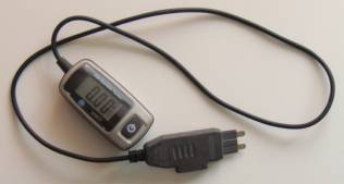
This is a commercially-bought lead (Maplins) used to measure the current passing through individual fuses. Its principal use is in tracking down components causing the battery to drain while the car is parked. The chief culprit so far has been CD changers wired into the boot light circuit.
Kerbside Motors Home Page and Contact Information
Contact Phil Payne by email or use mobile/SMS 07833 654800