The ABC's of Running High Boost for the
1991 200TQ 20V Turbo and the 1992-96 Audi S4/S6
- Introduction
- Stock Boost Levels-How does the ECU control Boost
- Boost Graphs, Stock and Modified
- Stock Boost Gauge, Aftermarket Boost Gauges,
Pressure Conversion Info.
- ECU Self Diagnostic System-Fault Codes, Output
Tests
- ECU System Components and Sensors Main page
with links to many topics
- Boost Problem Check List
- Overboost Fault Code? 2224? Check the boost hoses?
Check the MAF electrical connections?
- Waste Gate Controls
- Waste Gate Diaphragm Leak Testing
- Engine Control Unit (ECU) Vacuum/Boost
Line
- Turbo Bypass Valve, Intercooler leaks
- Boost Hose Leaks, Samco Hoses
- Vacuum Leaks-Breather Hoses!
- Are you using the correct Spark Plugs?
- Ignition Wires? Distributor Cap?
- Ignition misfire on S4/S6 with coil
over direct ignition system?
- Are you using the correct Distributor
Rotor on the 1991 200TQ 20V with 3B engine?
- Knock Sensor Intermittent? Hesitation? Low Power?
- Air Temp Sensor
- O2 Sensor Replacement
- Fuel Filter Clogged or restrictive?
Fuel Contamination?
- Fuel Pressure Regulator diaphragm leaking?
Regulator Vacuum/Boost Hose Leaking, disconnected
?
- Multi-Function Temp. Sensor-Defective (3B Engine)?
- ECU - Coolant Temp Sensor Resistance Check,
Wiring check
- Check ECU connector terminals
for corrosion
- Check Engine Ground Cable and Intake Manifold
Ground wires
- Throttle Cable Adjustment
- Throttle Switch/Potentiometer -
Defective?
- Check Basic engine timing, flywheel, camshaft
and distributor rotor position
- Altitude Sensor ok?
- Idle Stabilizer Valve (ISV)
- Idle Speed/Mixture Adjustment?
- Fuel Injectors
- Coolant Pipe O-Rings, Seal and Turbo
coolant hose replacement
- Thermostat and other Cooling system checks
- Failed Emissions Test? Go to
Smogsite.com a great web site
with Emissions and Fuel Injection
Info.
- Exhaust System Issues
- Drive Train Issues
- Important Safety Information
- Audi Parts
Introduction
It should be your responsibility (or your mechanics) to check out
and verify all the ECU and Fuel Injection system components mounted on
your engine are working correctly BEFORE you do any type of modification
that will raise the boost on your vehicle.
Raising the boost on a high mileage car isn't a great idea UNTIL you get
the stock system working correctly as it was originally designed when
it left the factory. If you install a stiffer Waste Gate spring or use
a valve connected to boost pressure to add pressure on top of the Waste
Gate Diaphragm, you may be unaware if the engine ECU/Fuel system components
are not working correctly, because the boost may be raised regardless
of the condition of the stock system components.
Whenever I purchase a used Turbocharged Audi, I check the compression
or do a leak down pressure test to verify the engine valves, rings, and
head gasket are in good shape. This leak down test is better than a basic
compression test and involves pressurizing the cylinder with air and measuring
the amount of leakage out of the cylinder.
This can pin point cylinder leakage out of the intake or exhaust valves,
past the rings, or through the head gasket. I replace the plugs, air filter,
and fuel filter and change the engine oil. I check/replace the O2 sensor.
I replace the valve cover gasket and any suspect breather or vacuum hoses.
I make sure the timing belt has been replaced at the suggested 60-90K
interval. I remove the lower Intercooler/turbo hose(s) and inspect them,
I check/replace the accordion style hose at the Intercooler connection.
It is also very important to check/replace the turbo bypass valve.
On the 1991 200TQ, it is important to Check/Replace the small Bypass valve
hose (vacuum/boost hose) that connects from the bypass valve to the small
fitting at the back of the intake manifold. On the 1992-95 S4/S6, you
may want to remove the black plastic firewall cover, and replace the crimped
on hose clamps at the ECU vacuum/pressure hose where it connects to the
clear moisture trap (Looks like a empty fuel filter) as these hose can
blow off as the boost goes up.
Audi Parts
You can also pressure test the intake/boost hoses, by making an adapter
that is inserted into the hose between the MAF and the turbo, and then
apply regulated compressed air (~15psi) and pressure test the hoses from
the turbo inlet, out the turbo exit hose, through the Intercooler, and
into the throttle. If you are running the 1+ type ECU mods, which produce
over 20psi of boost, using the Samco boost hoses may save your screamin
K24 turbo some day.
I check the operation of the idle/potentiometer throttle switch, and I
remove and clean the idle stabilizer valve. I check the ECU measurement
block values (10 values) to ensure the ECU is operating the engine as
expected. If a problem with the mixture adjustment shows up, the intake
vacuum hoses, or the fuel pressure may need to be checked.
The cooling system integrity should be accessed. Replacing the thermostat,
and all the coolant hoses, the heater control valve, the heater core to
engine hoses, the radiator fan temperature sensor, the after-run temp
sensor, and the Multi-Function temperature sensor is also a good idea
on vehicles with over 100k miles.
You don't want a $10 hose ruining your expensive 20V engine when the hose
blows and causes overheating and a possible blown headgasket! Once I complete
the replacement of these many high mileage components, and ensure the
engine/ECU is operating correctly, I can rest assured, and I don't need
to "guess" if they are ok if the car starts running poorly.
Don't get lazy and "assume" these components are ok, just bite the bullet
and inspect or replace them as necessary. NOTE: Increasing the boost on
your vehicle may change the emissions output which may not be legal in
your area.
Stock Boost Levels-How does the ECU control
Boost?
The 1991 200TQ with 20V Turbo Engine was
designed to run a maximum of 1.825 bar boost (absolute) or ~12 psi gauge
pressure, as set by the Motronic Engine Control Unit (ECU).
The 1992-96 Audi S4 in overboost mode will have boost set to about 2.15
bar absolute. The actual boost produced will vary depending on engine
RPM, air temperature, fuel quality, and altitude. The 20V boost control
system is different than what was used on the earlier 10V Audi Turbo engines.
The ECU uses the Waste Gate solenoid to send boost to the lower chamber
in the waste gate to open up the waste gate at the appropriate boost level.
The Waste Gate solenoid valve is designed to be open with no electrical
signal applied, which will send turbo boost pressure directly to the lower
chamber in the waste gate and open the waste gate at a pressure only determined
by the stiffness of the waste gate spring.
When the waste gate solenoid is energized with a high duty cycle, (more
on time) the waste gate solenoid will prevent boost pressure from reaching
the waste gate lower chamber, and allow the boost pressure to climb higher.
The boost will climb, until the required boost level set in the ECU is
reached, at which point, the duty cycle percentage (%) to the waste gate
solenoid will be reduced, so the boost pressure will once again be sent
to the lower chamber in the waste gate diaphragm and the boost pressure
will be controlled. In the stock 20V engines, this corresponds to about
1.4-1.5 bar of boost as controlled by the waste gate spring. If you completely
remove the lower waste gate hose, or block it off, the waste gate will
only open when "exhaust" pressure acting on the waste gate valve face,
exceeds the waste gate spring pressure.
This is why a modified 20V ECU can make 2.25 bar absolute boost pressure,
even with the stock waste gate spring installed. The ECU uses a barometric
sensor to monitor the altitude the vehicle is at, and will trim back the
boost slightly as the altitude increases above 3900 feet. For example,
in the 1991 200TQ 20V, the boost will be reduced to about 1.715 bar absolute,
when the altitude is above 8500 feet [1].
Stock Digital Boost Gauge, Aftermarket Boost Gauge, Pressure Conversion
Info.
The stock digital boost gauge located in the instrument cluster displays
the intake manifold "absolute" boost pressure, from ~0.0 bar to 2.0
bar. The S4 boost gauge will read up to 2.5 bar on the 1992 models.
Some of the later Canadian S4 models also have the boost gauge.
For more details, go to the Stock Boost Gauge
page
Self Diagnostic System-Fault Codes
The self-diagnostic system test should be run before you have your stock ECU
modified, to make sure that there are no faults in any of the components (knock
sensors, coolant/air temp sensors, throttle switch etc.) that the ECU relies
on for correct engine operation. You need to do a 3rd gear full throttle run
to exercise this diagnostic system correctly.
The 1991 200TQ's with the Bosch Motronic ECU, have a non volatile memory for
the fault codes that can be read later even if the engine has been turned off
after the test drive. The ECU system OUTPUT tests should also be done on the
stock ECU before doing any modifications to verify that the Wastegate Solenoid,
the Carbon Canister valve, the idle stabilizer valve and the fuel injectors are
working correctly.
In some cases the ECU internal drive transistors for these solenoids can be defective
and will prevent correct operation of the engines fuel and boost control systems.
If there is a problem with any of the solenoids or the internal operation of
the ECU, this needs to be known BEFORE you send in a ECU for modification.
Go to the
20V ECU Fault Code page at this web site
to run these Output tests.
Boost Problem Checklist
Here is a checklist you can go through when you have low or high boost
problems.
LOW BOOST or Running poor issues
- Check for any stored ECU fault codes, are the knock sensors working
ok?
- Read the Measurement block values using the VAG-COM, look for anything
out of the range
- Check basic engine timing, flywheel, camshaft and distributor rotor
position
- Check Throttle Cable Adjustment
- Check Air Filter, is it really clogged up?
- Check/Replace the Turbo Bypass Valve, check small vacuum/boost hose
to this valve
- Check Idle Stabilizer Hoses, and other small vacuum/boost hoses
- Check basic fuel pressure and correct operation of the rising rate
fuel pressure action by applying vacuum or boost to the vacuum/boost
hose connection
- Check fuel pressure regulator for leaking into the vacuum/boost
hose fitting (rich running)
- Check ECU moisture trap hoses (fuel filter lookin thang) behind
black firewall cover (AAN S4/S6)
- Check ECU Connector Terminals for corrosion, remove connector and
use contact cleaner
- Replace small vacuum hose from Bypass valve to Intake Manifold (3B
engine)
- Check the Operation of the Multi-Function Temp Sensor (1991 200Tq
20V Only)
- Temporarily disconnect Multi-Function Temp Sensor 4 pin connector
and recheck boost output (1991 200Tq 20V Only)
- Remove and inspect the Intercooler exit hose (Ribbed Hose) and the
lower turbo exit pressure hose for leaks.
- Check the rubber hose between the intake pipe and the throttle body.
- Check Vacuum hoses and their connections at the back of the intake
manifold
- Check/Replace the coolant thermostat, is the engine running too
cold? or too hot?
- Check Engine Coolant Temperature Sensor Resistance and connector
wiring
- Check the operation of the Waste Gate Solenoid using the ECU Output
Test
- Check Waste Gate Solenoid hoses
- Check Air Temp sensor resistance at the ECU, and Repair the Air
Temp Sensor wiring connections if needed.
- Check Throttle Position Switch/Potentiometer for intermittent operation
- Check Altitude Sensor Voltage Output and wiring between sensor and
ECU
- Plug or pinch off hose to lower waste gate and check for maximum
boost and overboost cutout
- Check Waste Gate for sticking open, defective spring?
- Check the Exhaust System Back pressure, possible exhaust restriction
- Inspect the Turbo inlet vanes and end play, has the turbo compressor
nut left the building? or the turbo seized up, broken in half, or
otherwise gone south?
OVERBOOST PROBLEMS (BOOST TOO HIGH)
- Check Lower Waste Gate Hose from Intake Manifold for leaks/restrictions
- Check the operation of the Waste Gate Solenoid using the ECU Output
Test
- Check Vacuum/Boost Hose from Intake Manifold to Engine Control Unit
(ECU) for leaks
- Pressure test the intake/boost hoses using hose adapter and compressed
air regulator adjusted to 15psi.
- Check and clean the electrical connections at the MAF sensor
- Check Waste Gate Diaphragm for Leaks
- Check Waste Gate Valve for sticking or restricted movement
Overboost Cutout?
ECU fault code 2224? If you are encountering an overboost condition
which is causing the ECU to cut the fuel pump, and you have stored
the
2224 ECU fault code, here are some items to check out.
You may have a leaking wastegate Diaphragm, test the wastegate diaphragm
for leaks below.
You could also have a leak in the boost hoses between the turbo
exit connection and the throttle
body.
If you have a hand pump or an air compressor, you can make up an adapter
to fit into the hose that connects to the turbo inlet, and this will allow
you to pressurize the air from the turbo inlet, through the turbo exit
hose, through the intercooler, from the intercooler exit hose, and from
the metal intake pipe to the throttle body and check for any leaks. Use
a pressure regulator set to about 15psi if you are using an air compressor.
You can also do a visual check of the turbo exit hose underneath the car
and look for any signs of oil leaking out of the turbo exit hose, indicating
a leak. Normally a small amount of oil vapors and mist are sucked in by
the turbo from the crankcase breather system, and this oil mist will typically
show up outside the hoses, or intercooler connections if a pressure leak
is occurring.
Check and or replace the ribbed intercooler exit hose as well, these often
split open on the bottom side, in-between the wire re-enforced rib areas,
due to the crankcase breather oil mist in the system. Removing the hoses
and inspecting them is also a good idea on high mileage engines.
If you don't have any leaks in these hoses, check the vacuum/boost hose
that connects from the back of the intake manifold to the ECU inside the
car.
See below for details.
I have run across a couple of 20V Turbo cars which had a 2224 code stored
inside the ECU and were getting the overboost fuel pump cutout, even though
the boost was only going up to 1.0-1.2 bar.
In the first case this would occur only when the throttle was quickly
floored, and would not happen if the throttle was gradually opened all
the way. In the first case, it ended up being a defective MAF sensor.
In the other case it was only a poor connection at the MAF sensor.
Try using some electronic contact cleaner on the MAF connector and terminals,
and see if the overboost problem is eliminated.
Waste Gate Controls
The Waste Gate solenoid connecting hoses should be checked for leaks and the
ECU Waste Gate Solenoid "Output Test" should be run on the Waste Gate Solenoid,
as these solenoids are often found to be defective on the 20V engine.
Go to
20V wastegate controls section for more details.
NOTE: On the 20V turbo 5 cylinder engines, there is NOT supposed to be any hose
connected to the top of the waste gate cap fitting. It should be left open to
the atmosphere.
LEAK TEST THE WASTE GATE
DIAPHRAGM
You can use a hand vacuum pump to test the waste gate diaphragm for leaks.
Connect the hand pump to the top waste gate chamber port and suck it down to
about 15-20in vacuum.
The waste gate upper chamber should hold vacuum. If it is holding vacuum,
you can quickly remove the hose and you "may" hear the waste gate
valve "CLUNK" back down to verify the waste gate is not stuck.
The waste gate valve normally moves about 15mm when it is fully open.
Go to the Waste Gate Spring Installation
page for details on inspecting the WG diaphragm if you suspect you have
a leak.
In some cases if a stiffer waste gate spring has been installed incorrectly
with no upper perch support, the waste gate valve shaft will operate with too
much force to the side and can wear out the wastegate valve guide. This worn
out guide can allow boost leaks through the waste gate.
In the US, the Audi dealer only lists the complete waste gate assembly available
for repairing a leaky waste gate diaphragm at a cost of over $1000, but these
diaphragms are available separately, go here
to for information on purchasing a new WG diaphragm.
Engine Control Unit (ECU) Vacuum/Boost
line
In order for the ECU to work correctly, it must receive an accurate pressure
signal (vacuum or boost) from the intake manifold. There is a plastic line with
rubber hoses on each end connected from the ECU to the intake manifold.
The vacuum/boost line (Green plastic line and rubber hose) from the intake manifold
to the ECU should be checked for leaks if you are getting too much boost or a
fault code 2221, 2222 or 2224. You can connect a hand vacuum pump to the line
after removing it from the back of the intake manifold and see if it holds vacuum.
If you have access to compressed air and have an accurate pressure regulator,
you can apply 10-15psi to the vacuum/boost line and listen for any leaks.
If you turn on the ignition, (Don't start the engine) you can read the boost
pressure off the digital instrument panel boost pressure display, and see if
it corresponds to the actual pressure applied to the ECU line from the air pressure
regulator. Be careful when applying pressure to this line, and avoid exceeding
20 psi or you could damage the internal ECU pressure sensor.
The 1991 200TQ 20V Motronic ECU has the moisture trap located next to the ECU
underneath the kick panel cover that can leak. The S4/S6 has the moisture trap
located underneath the plastic cover on the firewall at the back of the engine
compartment.
It is very common for the hose to get blown off the moisture trap on
the S4/S6 vehicles and cause the vehicle to have low boost and run
poorly in the "Limp
Home" mode. The S6 may have the moisture trap near the ECU. I recommend replacing
the crimped on clamps with conventional screw type hose clamps at this moisture
trap location.
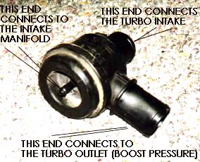
Turbo Bypass Valve and Intercooler
leaks
This valve should be removed and checked as this can cause a loss in boost
pressure if the internal diaphragm is leaking. Use a handheld vacuum pump connected
to the small hose fitting to check this valve operation. It should hold vacuum
and open and close freely.
This bypass valve relies on boost pressure acting on this internal diaphragm
to hold the valve closed when the engine is making positive manifold pressure
(above 1.0 bar absolute boost pressure) so you should check the small hose
connected to this valve.
The 1991 Audi 200TQ 20V often had problems with the vacuum/boost supply hose
for this bypass valve getting burned/toasted as the hose was run along side
the exhaust manifold area. Remove the heat shield and inspect/replace the hose
as needed.
Rerouting this hose away from the exhaust area is a good idea. This bypass
valve opens during manifold vacuum conditions (below 1.0 bar manifold pressure)
to allow intake air to circulate around the turbo cold side impeller.
This bypass valve helps to reduce turbo lag and keep the turbo spinning during
transmission shifting when the engine is producing boost. It also helps to
prevent boost pressure spikes from causing leaks or damage to the intercooler
or connecting hoses.
Audi Bypass Valve Info:
The 1991 200TQ 20V with 3B engine originally used a bypass valve with the Audi
part number 034 145 710 which had the metal reinforcement plate on the diaphragm,
this bypass valve may have had the Bosch 0 280 142 106 part number on it.
An Audi Service bulletin: Group 21 Number 00-01 Dec. 8, 2000 was issued that
described a problem with the Audi TT's that were equipped with the ATC, AMU
and AWP code 1.8T engines. A groaning, howling or rattling type noise may be
heard to come from the bypass valve.
A new Bosch bypass valve was introduced (Audi # 06A 145 710N) to address these
complaints. There is a Bosch equivalent part number for this new valve, and
it is reported to be a good replacement valve for other Audi turbocharged engines
utilizing a bypass valve.
Go to our on-line catalog HERE to
check pricing and availability for this new Bosch bypass valve.
Select 1991>Audi>200 QT 20V>Air Intake>Turbo Cut Off Valve
Select 1992>Audi>S4 Q Turbo>Air Intake>Turbo Cut Off Valve
Note: The normal failure with these plastic Bosch bypass valves, is the rubber
diaphragm develops a tear, either near the outside edge of the diaphragm, or
at the sealing surface.
A few aftermarket performance companies have a new all metal, version of the
bypass valves, one is called the "Bailey" valve, and one I believe
is called the Forge valve. I have not tested these valves, so I can't comment
on their effectiveness. The intercooler end cap seals can leak under high boost
and you should install some large straps or one or two large hose clamps around
the intercooler to hold it together under high boost.
Many hydraulic supply houses carry the screw type hose clamps that are 4 ft
long which fit around the intercooler nicely. Because there normally is an
oil mist flowing through the intercooler, any leaks around the intercooler
seals will show up as oil seepage out of the intercooler end caps.
In some cases you can carefully re-crimp the aluminum tabs that hold the plastic
end tanks on to tighten up the end cap seal. The internal intercooler rubber
seal on the inlet side that seals the internal upper and lower sections of
the intercooler should be checked when you remove the hoses from the intercooler.
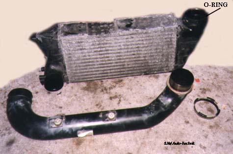
Here is a picture of the larger single pass intercooler from the 1991 200TQ
20V.
There is an O-Ring on the inside of the intercooler inlet on these intercoolers
that seals this pipe to the intercooler. This O-ring should be checked for
leakage and replaced if necessary.
The Audi Part number is N 904 324 01, designated as a round seal 70X4N
Boost Hose Leaks, Wastegate
valve boost leaks, Turbo intake hose
Often times on high mileage (100k>) cars, the turbo hoses begin to leak
boost pressure from loose hose clamps and in other cases when running higher
boost above the stock 12psi (1.8 bar absolute) levels, the original boost hoses
can tear and split open.
You can make a pressure test cap to pressurize the intake/boost hose system
to 15-20psi and look for any leaks from the turbo intake hose, to the turbo
exit hose, from the intercooler to intake ribbed hose, into the throttle valve
and finally to the intake manifold. You should remove the oil cap and pinch
off the breather hose at the intake manifold connection to avoid pressurizing
the crankcase.
This test cap can be made using a 3 inch black plastic sewer pipe cap, and
a bolt in tire valve stem. You insert this test plug into the turbo intake
hose after removing the hose from the MAF sensor. You may need to use a pressure
regulator with your air compressor to limit the pressure of the system to 15-20psi.
Common boost leaks: 1991 200TQ: The accordion-style hose that connects the
intercooler exit to the intake manifold normally rots (from oil) over time
and can split at the bottom between the ribs while under high boost. On the
later 1992-95 S4, the ribbed hose from the boost pipe into the intercooler
underneath the engine will often split in the ribbed area for the same reason.
Remove and check them. If your car has over 100,000 miles on it and this hose
has never been replaced, save yourself some grief and buy a new hose. Samco
has some heavy duty silicone replacement boost hoses for the Audi 20V's.
The turbo exit hose can also split on the 1991 200TQ 20V and on the S4's where
the bypass valve hose is melded into this turbo exit hose. Many folks are running
over 20psi with the stock K24 Turbo, and if you get a severe boost hose leak,
you can over-spin the K24 into destruction.
The OEM Stock 1991 200TQ 20V accordion hose is available, contact us for a
quote.
In some rare cases the Wastegate valve guide will be worn
excessively and will leak boost into the exhaust system. This
can be caused by using stiff wastegate springs with a loose or poorly
mounted upper spring perch in the wastegate cap.
Turbo Intake Hoses:
The large turbo intake hose with connections to the bypass valve, breather
pipe and Mass Air Flow sensor should be removed and checked for any cracks
as this will allow un-metered air inside the engine.
While you have the intake hose off the turbo, you may also want to check the
cold side turbo shaft for excessive play. The K24 turbo Audis spec the max
end play to be 0.00354 inches, and the cold side compressor side play to be
no more than 0.0259 inches. Normally you need a dial indicator to accurately
measure this.
You should also look for any metal shrapnel caused by worn turbo bearings which
may have allowed the turbo compressor blade to rub against the turbo housing.
The turbo exit hose (turbo pressure) going to the intercooler should be removed
and checked as well. The 1991 200TQ 20V has a metal boost pipe that is inserted
into the intercooler inlet uses an O-Ring for sealing this connection, see
section below for details if you see evidence of a leak at this point.
Vacuum Leaks-Breather Hoses!
You need to make sure your engine�s various breather/vacuum hoses and turbo intake
and pressure hoses are in good shape. Leaks anywhere in these hoses can cause
lean or rich running and poor starting. Vacuum leaks would typically cause lean
running, pressure leaks after the turbo could cause slightly rich running. In
some cases it is not sufficient to just visually look at these hoses without
first removing them!
On the 1991 200TQ 20V with the 3B designated engine, the large breather hose
coming from the side of the engine that is routed around the back of the engine
typically gets rotten and mushy on the inside part of the hose facing the engine
block.
Often times the hose can collapse on itself or will split open on the back side.
This hose does not have hard vacuum applied inside like the 10V Audi Turbo MC
engine but leaks could allow un-metered air into the engine.
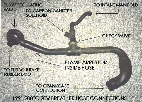
Here is a photo of the 1991 200TQ 20V breather hose, Audi part # 034 103 221AF,
Pressure or flow regulating valve (034 129101A), check valve or what Audi calls
the bleeder valve (035 103 245A) , and the small special molded hose (034 133
367C) , that connects to the intake manifold and the carbon canister solenoid
valve.
The spiral wire brush flame deflector inside the hose has Audi part number 035-103-477A
Always check with your Audi dealer parts person to verify these numbers.
This 1991 200TQ 20V breather hose is routed around the back of the engine and
one end connects to the round black crankcase pressure regulator valve near the
back of the valve cover.
This black regulator valve, controls the flow of crankcase fumes to the turbo
intake boot [1]. The valve has two ports inside, one is approximately 0.400 diameter
and a smaller one that is approximately 0.180 inches. The larger port and the
smaller port are open during low boost operation but when the turbo makes enough
boost and flows enough air to produce a vacuum on the suction side of the turbo,
the regulator valve diaphragm sucks closed and blocks off the larger port.
This leaves only the smaller port open to flow crankcase breather fumes.
Here are two diagrams showing the valve in operation under low boost and low
intact tract flow with both the 0.180 and the 0.400 ports open, the second diagram
shows the operation under high boost, high intact tract flow, high intact tract
vacuum conditions when the internal diaphragm is pulled against the 0.400 opening
to close it off, leaving only the smaller 0.180 port open for reduced flow.
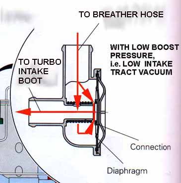

Diagrams courtesy of Audi of America
NOTE: On the 1991 200TQ 20V there is also a flame arrestor (spiral wire brush)
inside this breather hose on the end near the black flow regulating valve, so
be sure to remove this flame arrestor and install it in the replacement hose.
This flame arrestor prevents a back fire in the intake boot from traveling into
the engine crankcase. I have not verified if the S4 uses this same flame arrestor.
This 1991 200TQ 20V breather hose also has a Tee in the center of the hose, which
connects to the intake manifold via a flow regulating one way check valve and
a molded rubber hose. The check valve will close under positive manifold "boost" pressure.
On the 1991 200TQ 20V the carbon canister solenoid valve also connects at this
tee location. The carbon canister solenoid allows gasoline fumes from the fuel
tank that are stored in the carbon canister, to flow into the intake manifold
when the engine is running.
The carbon canister solenoid valve is closed when the engine is off to prevent
fuel tank fumes from entering the engine and causing a rich mixture when starting.
If the carbon canister solenoid or electrical connection should fail, this valve
also has an internal diaphragm which will open under engine vacuum to allow fuel
tank fumes to flow into the engine. It is very difficult to see this connection
to the intake manifold hose, as there is very little room behind the engine.
NOTE: On the 1991 200TQ 20V if you are working around the back of the engine
and replacing this breather hose, make sure you mark and identify any hoses or
electrical connectors before removing them. In one instance, I ran across a car
that had the electrical connectors from the heater valve temp sensor, the carbon
canister valve, and the engine coolant temp sensor mixed up and connected to
the wrong item.
The color coding on the connector, may not match up with the item it plugs into.
The Bentley manual shows that the Engine Coolant temp sensor connector should
have two wires, one Gray with brown stripe, one Green with black stripe. The
Carbon Canister solenoid connector has two wires, a Red colored wire and a White
with red stripe wire.
The heater valve coolant temp sensor electrical connector should have two wires,
a Yellow and red stripe wire and a Brown with black stripe wire. The two small
idle stabilizer hoses should be removed and checked also as they can get blown
off from the pressure. Any of the smaller hoses connected from the intake manifold
to the heater/AC system should be checked for cracks or leaks.
Are you using the correct Spark Plugs?
The 20V Turbo engines as found in the 1991 200TQ and in the later 1992-95 S4/S6
should have installed the Original Equipment F5DPOR BOSCH PLATIN Electrode
Spark Plugs.
Be aware, that they are more expensive than normal spark plugs. These F5DPOR
plugs have a single thick platinum electrode.
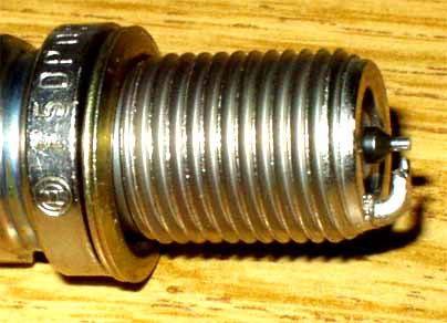
Bosch F5DPOR PLATIN Spark Plug
These thick electrode Bosch PLATIN plugs should not be confused with the cheaper
Bosch platinum spark plugs that have a thin center electrode. There are Bosch
3 electrode copper core plugs (FR5 DTC) that cross reference to the F5DPOR,
but I don't recommend using these 3 electrode copper core plugs, use the correct
single thick electrode platinum F5DPOR plugs.
It is also a good idea to check the torque of the spark plugs,
every 5k miles if you are running high boost levels, as many have found
the plugs to come loose on the 20V Turbo engines.
New Bosch F5DPOR plugs are spec'd to be tightened to 22 lb-ft, used plugs will
normally require slightly more torque when re-installing them.
It is also a good idea to replace the valve cover gasket on the 20V Turbo engines,
if you have higher mileage on your engine, and still have the original gasket.
The center valve cover gaskets around the spark plug holes can leak and mess
up the plug area and the spark plug wire ends. Audi
Parts
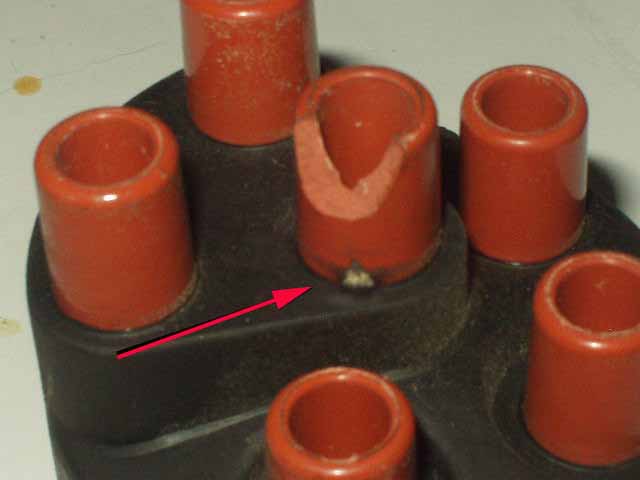
Ignition Wires causing misfire?
Distributor
Cap shorting out to black shield cover?
For the 3B engine, the Audi OE ignition wires have a stranded copper
wire and use resistive spark plug connectors that each have ~5k ohms.
The
other
end of the
ignition wire that plugs into the distributor cap has a resistive connector
end with approximately 1k ohms.
In many cases the spark plug ends can
have too much resistance and will cause a misfire under load, in some
cases the resistance measurement will test OK, but you will still get
a misfire due to the ignition wires or connectors.
On high mileage engines with the original ignition wire set, the spark
plug wires and connectors can arc to the valve cover under high load/high
boost.
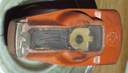
I have also found in rare cases that the distributor cap can arc internally
to the inside of the outer black plastic shield which can cause
strange running conditions
and
misfires that are very difficult to locate.
The distributor cap below was arcing from the coil wire center post
to the black cap shield.
It came from a 1991 200TQ 20V that exhibited
hard starting intermittently, would stall
at idle at random times,
and would
cutout under
full
throttle
conditions that felt like the fuel pump quit. The ECU would store
false fault codes for the RPM and Reference Sensors, as well as a
false fault
code
for
the
Hall
Effect
Sensor in the distributor. The arcing area was on the back side of
the cap and was not visible with it installed on the distributor.
1992-97 Audi S4/S6 Five Cylinder 20V turbo engine:
The
coil leads that connect from the coil to the spark plug also have internal
resistance (~5k ohms) which can fail and cause a misfire under heavy
load even if the resistance measures OK. Additional information below
covering other ignition problems.
Ignition misfire on S4/S6 with coil
over direct ignition system
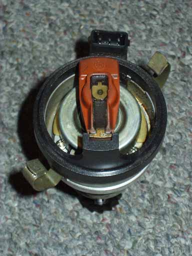
Are you using the correct Distributor
Rotor for the 3B 20V Turbo Engine in the 1991 200TQ ?
The 3B designated 20V Turbo engine in the 1991 200TQ used a unique Distributor
Rotor with a narrow tip that can be difficult to find in the US. This narrow
tip rotor is required to provide the precise ignition timing at the higher
RPM's and to prevent any ignition cross firing inside the distributor cap.
Some people have reported engine damage (bent rod) that may have been caused
when the incorrect cylinder was fired under very high boost.
The Bosch parts catalog shows the INCORRECT distributor rotor
(Bosch 04170 or the 1 234 332 350 R1) for this 20V Turbo application.
This Bosch 04170 (1 234 332 350 R1) rotor has a wider electrode tip measuring
0.710 inches (~17-18mm).
The Audi part number shown for this INCORRECT rotor is 052 905 225C
The correct Bosch Distributor Rotor with the narrow tip for the 3B engine,
has the last 3 digits as -414.
The correct narrow electrode tip rotor measures only 0.432 inches, (~11.0mm).
The Bosch part number may also have the designation "R1" at the end,
which indicates the rotor has a 1k ohm resistive element from the center to
the tip.
Audi Parts on-line catalog:
Using our on-line catalog:
Select the 1991>Audi>200 QT 20V>Engine Electrical>Distributor Rotor>Distributor
Rotor-Only on this Application
The original 3B distributor rotor with narrow tip. The other important thing
to note about this rotor, is that it is glued onto the distributor shaft, and
it needs to be broken or crushed when removing it from the shaft using a pair
of channel lock pliers. You can also use a dremel cutting wheel to cut off
the old rotor.
Be careful not to damage the shaft when crushing this rotor and removing the
left over pieces. You need to thoroughly clean the distributor shaft with some
sand paper and some non residue cleaning solvent, (loctite primer solution
is also recommended) and then use Loctite 640 (or equivalent) to secure the
new rotor in place.
The Loctite needs at least 4 hours to dry before you can start the engine.
This operation is not easy given the restricted access to the distributor on
the 3B 20V Engine. You can remove the intake manifold to allow easier access
to the distributor.
NOTE: Even though it is possible to pry off the anti-tamper plate from over
the distributor hold down nut with the intake manifold installed, I recommend
taking the extra time and remove the intake manifold to allow easy access to
the ignition distributor.
With the intake manifold removed, you may want to replace the coolant pipe
O-Rings, seal and Turbo coolant hose while you have the intake manifold removed.
See section below for details. When you unbolt the intake manifold, you can
leave the fuel lines attached to the intake fuel rail, and just use some heavy
wire to tie up the intake manifold out of the way as shown in the Bentley repair
manual.
A long (over 8 inch) 6mm allen wrench tool is usually required to remove the
intake manifold bolts. (VAG1669 or equivalent). You can also use a long 1/4
inch drive extension, with a 6mm socket and a 6mm allen wrench socket shaft
in combination to access these intake manifold bolts but this is a little tricky.
The intake manifold gasket should be replaced and the bolts should be torqued
to 16 ft-lbs upon reassembly, start in the middle and work your way outward
when torquing them down. Once you have the intake manifold tied up out of the
way, you can cut off the anti tamper cover (a Dremel cutting wheel works here
as well).
Before you loosen the distributor hold down nut, you should first set the engine
to be at TDC with the flywheel O mark lined up, and the distributor rotor pointed
at the line mark on the rim of the distributor. Once you get the engine rotated
to the correct position, you can remove the hold down clamp and pull out the
distributor. Removing the distributor gives you better access to the distributor
so you can either crush the old rotor with some pliers, or cut the old rotor
off "carefully" using a dremel cutting wheel.
As mentioned, you should remove all traces of the old rotor with some 200-300
grit sandpaper, and use some non-residue solvent (loctite primer solution is
also recommended) to clean the distributor shaft before you apply some Loctite
640 to the inside area on the new distributor rotor. Insert the rotor over
the distributor shaft with the key way lined up. Allow to dry for at least
4 hours before starting the engine.
The Bentley Repair manual also indicates that you should use the special tool
#3233 to accurately line up the distributor rotor tip when setting the basic
distributor position in relation to the flywheel O TDC mark, and the cam gear
dot mark.
The Bentley also states that you should turn the distributor body counter-clockwise
when you line up the rotor with the 3233 tool and then hold the distributor
body with your hand while you tighten down the hold down nut. NOTE: The R1
in the distributor rotor part number refers to the fact that this rotor has
a 1K ohm resistor between the center electrode and the outer tip electrode.
This rotor resistor can sometimes burn up after many years and cause a no start,
and prevent the engine from running. You may also want to replace the valve
cover gasket, the main breather hose, any vacuum hoses and other hard to reach
coolant hoses and coolant temperature sensors while the intake manifold is
moved out of the way.
See section below for replacing the Coolant Pipe O-Rings, seal and turbo coolant
hose while you have the intake manifold off.
Coolant Pipe O-Rings, Seal and Turbo coolant
hose replacement
Knock Sensor Intermittent? Hesitation?
Low Power? Check Engine light On?
If your 1991 200TQ 20V is running poorly or the "Check Engine" light
has come on, it is possible that the ECU is detecting a fault in the
knock sensor system caused by a loose, defective or intermittent knock
sensor. There may also be a problem with the knock sensor wiring or connectors.
Go to
20V Engine Knock Sensors section for details
on the 20V Turbo Engine knock sensors.
The newer style "replacement" knock sensors have gold plated terminals and the
wiring harness connector terminal pins should be replaced with these gold plated
versions as well.
Audi parts on-line catalog
Some of the 1991 200T/Q's have the "Check Engine" light bulb removed from the
dash, so if the car is having a problem with one or both of the knock sensors,
you may not know it.
The "Check Engine" light should come on with the ignition key turned on to the
first position.
Air Temp Sensor
The air temp sensor that the ECU monitors to regulate boost and ignition timing
can have poor external connections or can have intermittent connections on the
small thermistor at the tip of the sensor. This sensor is located in the intake
manifold near the throttle valve.
The wire terminals are normally soldered or spot welded to the air temp sensor.
Factory replacement air temp sensors use a separate connector with gold plated
terminals instead of the soldered/welded terminals on the original sensor.
Go to the
20V Air Temperature sensor page for details
on checking the operation of this air temp sensor.
O2 Sensor Replacement
The O2 sensor should be replaced if it has over 60k miles on it, or if you
have a hesitation, lean surging during light throttle conditions,
poor cold running
problems during the first 30-60 seconds of engine warm up, poor gas mileage
or emissions related failures.
Older O2 sensors can get contaminated and will
respond too
slowly
to correctly
adjust the mixture and can cause poor running when transitioning from light
throttle to full throttle conditions.
Audi parts on-line catalog
See these sections for details on testing and /replacing the O2 sensor.
Oxygen (O2) Sensor, Open and Closed
Loop Operation
Oxygen (O2) Sensor, Testing
Bosch Replacement 3 Wire Oxygen Sensor
Fuel Filter clogged or
restricted?
Fuel contamination?
A clogged or restricted fuel filter can cause cutting out under high load
and high boost in 3rd/4th/5th gear that often may feel like an ignition misfire.
It is a good idea to change out the filter every 30k miles or every 2 years.
The filters are normally designed to absorb any moisture in the fuel which
can cause the filter media to swell and restrict fuel flow.
The ethanol based fuel can make this issue worse. After removing the filter,
if you can't easily blow through the filter, it needs replacement.
If I suspect fuel contamination with excessive water or dirt etc, I like to
remove the filter and "carefully" blow the remaining fuel out of
the filter into a clear glass bottle to check for any crud/water.
Fuel Pressure Regulator
Diaphragm Leaking, Running rich?
Regulator Vacuum/Boost hose leaking or disconnected,
Poor running, cutout under full load?
In some cases the fuel pressure regulator diaphragm is ruptured and will leak
fuel into the vacuum/boost port and get sucked into the engine at the other
end of the hose where it attaches to the intake manifold. Check the vacuum
port for any fuel after removing the vacuum/boost rubber hose line.
Also verify the vacuum/boost hose from the intake manifold to the fuel pressure
regulator vacuum/boost port is not leaking.
If the fuel pressure regulator does not get good engine vacuum at idle, this
will cause the fuel pressure to be increased and this would cause rich running
at idle.
The regulator also requires boost pressure acting on the diaphragm to ensure
the fuel pressure is increased above manifold boost pressure to maintain the
fuel pressure drop across the injector.
Insufficient fuel pressure under high load, high boost can cause cutting out
in 3rd/4th/5th gear.
The S4/S6 incorporates a screen inside this pressure regulator which could
get clogged with extremely contaminated fuel.
Audi parts on-line catalog
Multi-Function Temp. Sensor-Defective?
One additional sensor to check when having low boost problems (1991 200Tq
20V Only) , is the Multi-function Temperature sensor.
This sensor is mounted underneath the intake manifold, on the coolant
pipe on the 20V Turbo Engine.
This Multi-function temp sensor uses a 4 terminal connector which is normally
is covered with a protective rubber boot. The newer style replacement
Sensors will have only 3 terminals as they simplified the internal design
of this sensor and eliminated the +12V supply to this sensor.
Go to 20V Engine Multifunction Sensor section
for more details on this sensor.
Audi Parts
Coolant Temperature Sensor:
The Engine Control Unit uses a coolant
temp sensor that should be tested if cold or hot start problems or
problems
during
engine
warmup
are occurring.
Go to 20V Engine Coolant Temperature Sensor section
for details on checking this sensor.
The engine must warm up quickly and run hot enough for correct boost
control and timing control and best performance. To ensure correct
operation and for the highest fuel mileage,
only
use the 87 Celsius Thermostat
See cooling
system section below.
Check ECU Connector Terminals
for Corrosion
If you are having some running or boost problems, you may want to inspect the
ECU Connector terminals for any subtle corrosion on the tin plated terminals
and use some electronic contact/terminal cleaner on them, along with some contact
enhancer.
The plastic bag cover over the connector should be installed correctly to avoid
any water or moisture from dripping down onto the connector and wiring. Sometimes
just removing the large ECU Connector will cure some problems as the action
of removing and installing the large connector wipes clean the connector terminals.
Check Engine Ground Cable and Intake Manifold
Ground wires
Throttle Cable Adjustment
It is a good idea to check the throttle cable adjustment to ensure
the throttle is being opened all the way when the gas pedal is pushed
all the way down to the floor. With the engine off, have a friend push
down on the gas pedal inside the car, while you check the throttle
lever under the hood. The throttle lever should be pulled all the way
open with the gas pedal pushed down all the way to the floor
Idle Switch or Throttle Potentiometer
Defective?
The Throttle switch/Potentiometer has 2 functions, (1) the idle switch tells
the ECU that the throttle has closed so it can perform deceleration fuel
cutoff and correct idle speed regulation.
(2)
The Potentiometer (variable resistance) tells the ECU both the throttle position
and the rate the throttle is opened and closed.
This resistance measurement is used with the ECU voltage supply to provide
a varying output voltage the ECU reads to set the correct amount of boost produced.
A defective Throttle Potentiometer may prevent the correct operation of the
Waste
Gate
(WG) solenoid
system that
the
ECU uses
to adjust
the turbo
boost.
Go to 20V Throttle Switch/Potentiometer page for
details on checking the Throttle Potentiometer.
Note: Using a stiffer Waste Gate spring is a great idea on the MC engines and
possibly on some 20V engines with non-stock Turbos as it will improve the rate
at which boost is produced, but...... it can mask problems with the ECU system
components (Throttle switch/throttle potentiometer etc.) as the boost will
be mostly controlled by the stiffer Waste Gate Spring.
Audi parts on-line catalog
Check basic engine timing, flywheel,
camshaft and distributor rotor position
You should check the basic engine timing, the flywheel should be placed
at TDC with the O mark lined up in the transmission window, the camshaft
gear line should be set at the top mark on the valve cover, and the distributor
rotor should be set to the #1 cylinder line on the rim of the distributor.
I have run into a few 20V engines that had loose front crank damper pulley
bolts, which allowed the crank timing gear to move side to side and shear
off the keyway which altered the crank/cam timing. It is likely that the
previous timing belt repair work was done incorrectly, and the mechanic
did not torque the crank pulley bolt enough.
The line on the dual mass flywheel in the AAN S4/S6 20V turbo engines
can be tough to see through the hole in the transmission housing when
setting the engine to TDC, it helps to put a white paint mark on this
line. In some cases on the 3B 20V Turbo engines, the timing belt will
stretch over time, and will change the cam/distributor timing enough to
cause problems for the ECU when it processes the distributor hall effect
signal to set timing and boost.
The Bentley manual has the details on setting these 3B distributors correctly,
normally this is done when the timing belt, or distributor is replaced
or if the camshaft is removed. A special tool #3233 is normally used to
line up the distributor rotor with the line on the distributor body, which
can help as it is difficult to see the distributor behind the intake manifold.
See photo below
If you don't have the 3233 tool, a small mirror can also be used to correctly
line up the distributor rotor and the line the rim of the distributor.
See section below on using the correct distributor rotor for these 20V
"3B" designated engines.
Altitude Sensor ok?
Idle Stabilizer Valve (ISV)
The idle stabilizer valve (ISV) can also stick from oil/crude built
up inside and this can cause strange high idle conditions.
Cleaning the ISV with carb cleaner may help.
With the ISV removed from
the engine, but with the electrical connector on, I like to run
the ECU Output Tests which cycle this ISV open and closed while you spray
the cleaner inside.
The hoses on the ISV valve to the intake manifold can blow off under
boost, or can be cracked and cause a loss in boost pressure. This engine
uses the ECU to control the idle stabilizer valve, which is a rotary
type valve.
Go to 20V Idle Stabilizer System section
for
details on checking the operation of this rotary valve
Idle Speed/Mixture Adjustment/Check:
NOTE: The Idle speed and Idle mixture on the 20V engine are not adjustable.
The 20V Motronic Engine Management system has the capability to adjust
the fuel mixture over time (adaptive system) so periodic adjustments have
been eliminated [1].
Fuel Injectors
Leaky injectors can increase the hot/cold starting times but the
20V engines are not as susceptible to this leaky injector problem as the
previous 10V Engines. Some high mileage vehicles or vehicles that are
driven over repeated short distances without proper warm up may exhibit
fuel spray problems. Dirty/clogged injectors with poor spray patterns
can cause poor low end performance and uneven performance when cold. There
are several companies that offer fuel injector cleaning and balancing
etc.
Excessive Intake valve carbon deposits can also cause cold running problems
as the carbon acts like a sponge, soaking up the fuel at first. With severe
carbon buildup some repair shops can use a walnut shell blasting device
to clean off the carbon buildup. Lighter buildup can be removed with the
use of a fuel additive or a fuel with Techron.
Coolant Pipe O-Rings, Seal and Turbo
coolant hose replacement
Cooling System checks
The engines cooling system needs to be working correctly before you decide
to up the boost on your car.
All the coolant hoses should be checked/replaced and the cooling system should
be flushed out and refilled with the correct mix of coolant. When you have
the upper radiator hose removed, check the condition of the plastic upper radiator
hose fitting, as these plastic fittings can crystallize and break off while
driving.
On the 5000TQ and the 200TQ, the plastic heater valve located at the back of
the engine near the exhaust waste gate should be replaced if it has high mileage,
they have a bad habit of getting brittle and breaking, causing a loss of coolant
and some rapid overheating.
The S4/S6 have this heater valve located away from the heat of the engine underneath
the plastic cowling near the windshield, so they may not need to be replaced
as often.
The S4/S6 do have a plastic Tee fitting that has the Climate Control temperature
sensor, which can get brittle over time and break that will cause you to lose
most of your coolant while driving.
This Tee fitting should be replaced on high mileage cars to avoid a sudden
loss of coolant. We keep these in stock , if you need one.
The Heater hose fitting at the back of the engine block is also plastic and
can crack internally which will cause a coolant leak, best bet is to replace
both of these plastic fittings.
Audi parts on-line catalog
The thermostat should be replaced with the factory specified 87 degree Celsius
version if you still have the original one installed, or if it is several years
old. Often times a malfunctioning thermostat will cause engine running problems,
and poor gas mileage if the engine is running too cool.
You may also want to replace the short piece of coolant hose located underneath
the intake manifold, as this hose can blow and make your life miserable if
you have to change it when the engine is hot.
Audi sells the hose in bulk lengths, or you can look for similar sized coolant
hose from an aftermarket parts supplier, Gates etc. I don't recommend using
fuel line or other hose not designed for high temperatures. The after run cooling
fan and turbo pump should be checked for correct operation.
Go to the Cooling system page in the Troubleshooting
section for additional details.
Exhaust System Issues
You should have the exhaust back pressure checked by a muffler shop if
you have low boost conditions and suspect a plugged catalytic converter
or muffler/exhaust system. They can use the pre-catalytic converter sniffer
pipe bolted to the intake manifold to do this, or they can drill a small
hole in the exhaust pipe to insert the pressure gauge pipe.
A low pressure (0-10 psi) fuel pump pressure gauge can be used for this.
Typically with the car idling in neutral, as you slowly rev the engine
to 4000 RPM and hold it at 4000 RPM, the exhaust back pressure should
not increase above 1-2 psi. If you run a long hose from the sniffer pipe
to a gauge inside the car, an assistant can check the exhaust back pressure
while you drive the car.
Test Example: When the car is driven and under load in 3rd gear at WOT
and near redline, it is not unusual to see over 4-7psi of back pressure
when running 1.8 bar of boost pressure. The older catalytic converters
can create some of this back pressure and may need to be replaced as the
car gets over 75K miles.
The RS2 type exhaust manifold is recommended for improving the exhaust
flow out of the head and rumor has it, to prevent burned exhaust valves
when more extensive ECU and Turbocharger mods are performed. As mentioned,
the catalytic converter and muffler system can get plugged or restricted
over the life of a car which may cause poor running with low power.
Catalytic Converter meltdown can occur if extremely rich mixture levels
occur in the combustion chamber which are not thoroughly burned which
allows high levels of raw gasoline (Hydrocarbons) to pass into the catalytic
converter. If this occurs under engine load conditions and is followed
by normal lean running or idling the catalytic converter will get very
hot and damage may occur. Ignition misfires can also dump raw fuel or
hydrocarbons (HC) into the catalytic converter and this will also cause
meltdown of the ceramic honeycomb material if the engine is driven under
load.
If you ever need a reminder to let your engine run after a high boost
run, just open up your hood at night and see the red hot exhaust manifold
and turbo! Even with the water cooled turbo you should let the car idle
for several minutes.
It may take 10-15 minutes of normal low boost driving before the exhaust
manifold/turbo cool down. It is a good idea to avoid high boost initially
after starting a cold engine until the oil temp gets up to 60C (this is
recommended in the factory operators manual).
Drive Train Issues
Driving with more boost/horsepower places more stress on the transmission,
clutch, suspension system and tires. The Audi I5 turbo engines are very
robust motors but running Higher Boost levels obviously places some additional
stress on the internal engine components.
The two hydraulic engine mounts and the rear transmission mounts should
be checked, the exhaust side (passenger side) engine mount is subjected
to a lot of heat. A defective hydraulic engine mount on this side tends
to place more stress on the exhaust manifold/system.
Of course the tires, CV joints, wheel bearings, shocks, sub frame bushings
and other suspension bushings/parts subject to wear and tear should be
replaced where necessary. Having more power will make the car a handful
to drive if you have a worn out suspension as you will discover in short
order.
Better to fix it now than to crash and burn it later.
References: [1] Audi of America, Technical service training publication:
"The New 20V Turbo Engine for the Audi 200 Quattro-publication
All rights reserved.
Copyright © SJM Autotechnik™ , all rights reserved
Return to
Troubleshooting Tips page.
Return to
SJM Autotechnik™ main page.